In-Duct UV-C Air Purification - A Beginners Guide
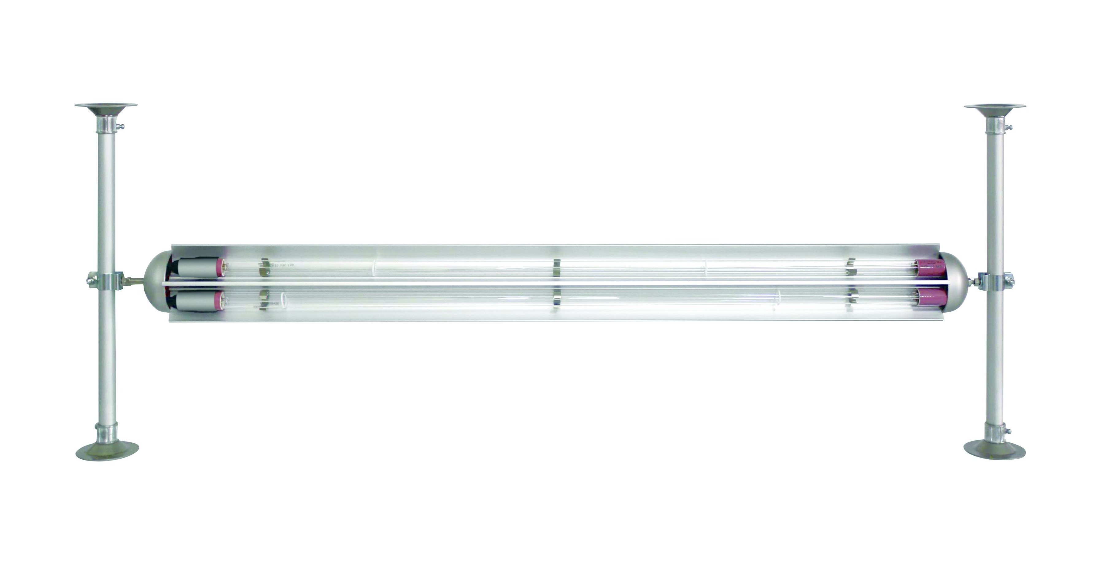
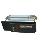
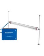
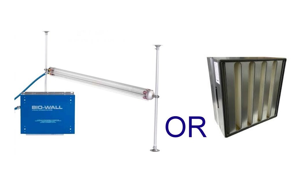
Two Sanuvox Biowall in-duct UV-C arrays in a duct section
The task of sourcing commercial in-duct UV-C air purification equipment for the first time can be bewildering. There is a wide array of options for what is a complex technology to treat an airborne problem that you cannot see but which you know will be there.
It is a lot to grapple with and the potential for making an expensive and ineffective mistake is high.
In this Covid-19 era the air purification market is a jungle. This guide will help you avoid the pitfalls and to find a system that will be effective and which has a known performance efficiency in your particular application.
Avoid the in-duct UV-C 'Elephant Traps'
- Specifying a UV-C system to treat an air flow in a duct is NOT a simple process. If your potential supplier asks little but just says you need a 'Whizzo bug blitzer 34X' or whatever, find an alternative supplier. The 'Barry from Cillit Bang' approach to selling UV-C equipment should ring very loud alarm bells. It is the No.1 clue to spotting the clueless supplier.
- If your potential supplier does not specify the In-Duct UV-C equipment specifically to your application, find an alternative supplier.
- If your potential supplier is pumping out 99.999% etc. efficiency claims without clear and stated context of the exact conditions in achieving the claimed efficiency, find an alternative supplier. The efficiency of all in-duct UV-C systems are dependant on the parameters of the application in which they are used.
- If your potential supplier does not ask you about the following details of your application, find a different one that does.
The In-duct UV-C Variables
The variables for treating air-borne micro-organisms with in-duct UV-C are as follows;
- Air flow. We need to know what airflow is moving through the duct.
- Duct dimensions. We need to know the width and the height of the ducting, or if it is round duct, we need the diameter. This information is vital for calculating the air speed through the duct and past the In-duct UV-C equipment. Also we need to know the straight length of duct where the in-duct UV-C is to be fitted. This is so we know how much available length there is to accommodate the equipment
- Duct materials. The inside surface of the ducting is a vital of often overlooked aspect of in-duct UV-C design. The materials that are best for reflecting white light are a very poor guide to the materials that are suitable for reflecting UV-C light. For instance stainless steel has UV-C reflectivity of 20%, galvanised mild steel 57% and aluminium 85%. The material, and therefore the reflectivity, of the duct walls has a large impact on the efficiency of the system installed and therefore affects how much UV-C we specify.
- Target micro-organism. There are hundreds of different types and each has a known amount of UV-C dose required in order to achieve its deactivation to a particular % efficiency. The amount of UV-C required for different viruses, bacteria and spores varies over a very large range. For example if you are looking to achieve 99.99%, 1 pass deactivation on Covid-19, we would be specifying an in-duct system that can deliver at least the required dose of UV-C to treat Covid-19 to this efficiency. But that same system will also treat the other airborne micro organisms present to a greater or lesser efficiency. We have lots of tables of this type of information and can show how a target ranks in amongst others so you get a feel of the overall effectiveness of the specified in-duct UC-V unit for different challenges.
- Air temperature range. The output from UV-C lamps varies depending on their temperature. If we know the air temperature, we can adjust the selection of unit to suit.
- Upstream filtration efficiency.
- For specifying an induct UV-C system we need the air to be filtered to ideally F7 standard. This ensures that the air is clean enough to minimise dust settlement on the UV-C lamps, which would otherwise impair their UV output. If there are HEPA filters upstream then this is useful to know because it narrows down the definition of the challenge and we can factor in the HEPAs effectiveness at catching the target micro organism with the in-duct UV-C efficiency at deactivating those that the filters do not catch.
- Duct function. What we mean by this is - what kind of air is the duct carrying? Fresh, recirculated air, or a mix of both. Understanding this impacts the unit selection.
What to look for in the product selection
A product selection for a particular application will include;
- The quantity and model of in-duct fitting with dimensions.
- The recommended placement within the duct section with dimensions.
- The air velocity of the air passing the UV-C array.
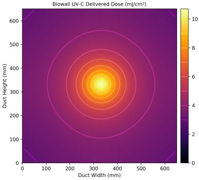
- The minimum, maximum and average UV-C dose mJ/cm2 delivered to the passing air.
- Input power to the UV-C array.
- The efficiency of the UV-C array in your application for the chosen target airborne micro organism(s), at first pass and successive multiple passes..
Features to look for in a in-duct UV-C air purification unit
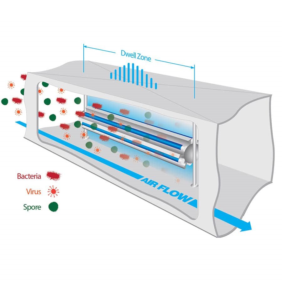
- Lamps must be in direction of airflow. There are a number of reasons for this.
- The operating temperature of the lamp will be maintained at a much more even temperature and will not suffer wind chill effects and cold spots typical of UVC lamps at right angles to the airflow. A uniform operating temperature is critical to ensuring ensure a longer life for the UV-C lamp.
- Lamps parallel to direction of air flow ensures highest possible UV-C dose from the lamps because of longer 'dwell time'.
- Safer - Lamps parallel to air flow are far less prone to being damaged or broken should debris inadvertently be carried on the airflow.
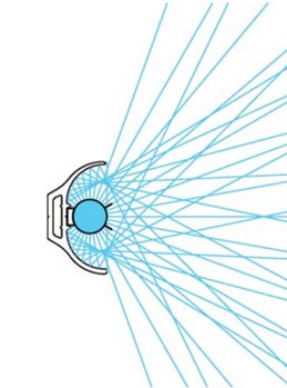
Parabolic reflector is vital for utilising all the UV-C light generated by the lamps
- Lamps must be supported and held with in a parabolic reflector ideally made from extruded aluminium section.
- This ensures that all the light emitted from the lamp fitting is used and projected to best effect through the passing airstream. Without a parabolic reflector it is similar to a torch bulb without a reflector i.e, feeble
- The reflector provides rigid protective support for the lamp both in transport before installation and in use in the duct.
- The array of lamps should be sufficient to ensure that the complete face area of the duct is basked in UV-C light for the complete length of the fixture.
- The system should have a control box;
- complete with ballasts to run each of the lamps in the array.
- with dry contacts to allow for connection of BMS.
- should have contacts to allow connection of safety door switch.
- should have connection socket to allow a remote monitoring with a control screen.
Outward projection of UV-C light to inside of duct walls
- The array of UV-C lamps should have a robust support structure for secure fitting in the duct.
- The option to fit self adhesive aluminium lining to the inside surface of the ducting. This has a very significant impact on the overall efficiency of the installation
Articles related to this product
-
 The topical background to UVC HVAC systems is that with the onset of cooler weather the widely recommended option of supplying 100 % fresh air ventilation in order to make buildings safe from the COV-2 threat is looking increasingly expensive.11/03/21
 -
 A guide to choosing between HEPA filter & UVC filtration. Can you combine the two, or is it a straight choice? We help your understanding.12/03/21